Contents:
- General Settings
- Alarm Settings
- Directory Settings
- Server / Client Settings
- Log File Settings
- More Options Settings
Additional Information
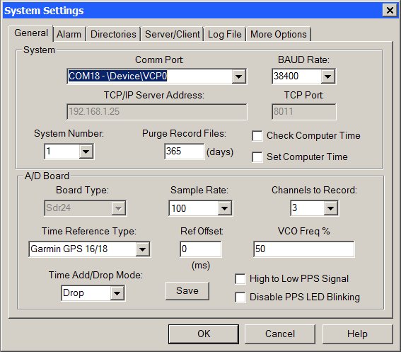
This tab of the System Settings dialog box is used to set the number of channels to record, sample rate and other system wide settings.
System Group Box:
Comm Port Select Box:
Sets the RS-232 communication port that will be used to communicate to the ADC board. If set to None - Replay Only Mode, WinSDR will go into a Replay Only mode. In this mode WinSDR can only be used to Replay daily record files generated by another WinSDR system located on a LAN. This field is also used to enable the TCP/IP COMM Client mode. This item will be the last line in the select box. When selected the TCP/IP Server Address and TCP Port number fields will be enabled. With this feature WinSDR can connect to a ADC board using a RS-232 to Ethernet adapter bridge device.
BAUD Rate Select Box:
Sets the RS-232 communication port speed. WinSDR will display an error message if you select a baud rate that is too slow for the number of channels being recorded and the sample rate. This field will be disabled in the TCP/IP COMM Client mode.
TCP/IP Server Address Edit Box:
This field is used to enter either the IP address or host name of the RS-232 to Ethernet Adapter. The adapter must be placed in the server mode so WinSDR can connect to the device. This field will be enabled when the TCP/IP COMM Client mode is selected in the Comm Port select box.
TCP Port Edit Box:
Used to enter the port number for the TCP/IP connection to the ADC board. This field will be enabled when the TCP/IP COMM Client mode is selected in the Comm Port select box.
System Number Select Box:
Used if you are running more then one copy of WinSDR. Each WinSDR system, either running on the same computer or on another system located on a LAN, should have a unique system number.
Purge Record Files Edit Box:
Controls how many days worth of data to save. Data from the ADC board is saved in a daily record file. WinSDR uses the data in the record files to create PSN formatted event files and for Replay and Real-time window display. The value in this field should be based on how much disk space you would like WinSDR to use. Depending on the sample rate and number of channels you are recording, the daily record file can be anywhere from a few megabytes to over 80 MB if you run all 8 channels at 100 SPS.
Check Computer Time Check Box:
If checked, WinSDR will check the local computer time with the time on the ADC board. The time difference will be written to the winsdr.log file and displayed in the Log File Display window every 5 minutes. The line below is an example of the time difference message:
DLL: Time difference between A/D Board and Host Computer=0.026 seconds
Set Computer Time Check Box:
If checked, WinSDR will set the local computer time if the time difference between the A/D board and WinSDR gets larger then 250 milliseconds. This check box should be checked if you are using GPS or WWV references. This check box will be disabled if you use the Local computer as the time reference.
A/D Board Group Box:
Board Type List Box:
This list box controls or displays the ADC board type. This list box will be grayed out once WinSDR knows what type of ADC board is connected to the Comm port. If the board type is unknown you can force WinSDR to use either ADC board.
Sample Rate Select Box:
Sets the sample rate that the will be used to convert the incoming analog signal to digital data. This field can be set to 5, 10, 20, 50, 100 or 200 SPS. Note: Version I boards can only record up to 4 channels at 200 SPS. PSN-ACCEL and PSN-ADC24 boards can sample at the following rates: 15, 30, 60, 100, 120 or 200 SPS.
Channels to Record Select Box:
Sets the number of channels that the A/D board will record. This field can be set to 1 through 8. Note: Version I boards can only record up to 4 channels at 200 SPS. PSN-ACCEL and PSN-ADC24 can have 1 to 4 channels on the board.
Time Reference Type Select Box:
Controls the time reference source that the A/D board should use for time keeping. Current options are: Computer Time, WWV, GPS Garmin 16/18, ONCORE Binary or ONCORE NMEA.
The Computer Time option uses the time of the system that is running WinSDR as the time reference. The WinSDR system should be connected to some type of time reference source. This could be a GPS system or a NTP (Network Time Protocol) program. To use NTP, you must have a full time Internet connection.
To use the WWV mode you must have the WWV timing option on your A/D board and a short-wave receiver tuned to one of the WWV frequencies. See this page for more information.
The Garmin 16/18 option uses a Garmin GPS 16 or 18 OEM antenna/receiver combination for time keeping. See this page for more information.
The GPS ONCORE Binary and NMEA options uses a Motorola ONCORE receiver for time keeping. See this page for more information.
Note: The Computer Time option should be selected if no timing reference source is available.
Reference Offset Edit Box:
Used to compensate for the travel time of the radio waves of the WWV/WWVB time standard transmissions and the tone detector's capture time. This number is in milliseconds. The tone detector has a capture time around 20 to 25 ms. You should add 1 ms for every 300km (186 miles) between you and the transmitting station. GPS users should place a 0 in this field.
Add/Drop Interval or Vco Freq % Edit Box:
Time Adjust Add/Drop Interval time or VCO Frequency Percentage. See below for more information on this setting.
Time Add/Drop Mode List Box:
Time Adjust Add/Drop Interval mode. See below for more information on this setting.
Save Button:
This button saves the new Add/Drop Time Interval and Mode to the time.dat file.
High to Low PPS Signal Check Box:
This check box set the direction of the GPS 1 PPS signal applied to the ADC board. The Garmin GPS 16/18 models supply a positive signal at the top of the second. The ONCORE receiver with the Webtronics ONCORE Interface board supplies a negative going signal, so this check box should be checked when using this timing system.
Disable PPS Led Blinking Check Box:
When checked, the LED on the ADC board will not blink at the top of the seconds. This feature was added because the 1 PPS signal can show up in the version I A/D boards event files with high gain Amp/Filter channels. This is not a problem with the version II boards.
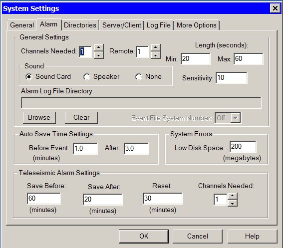
This tab of the System Settings dialog box is used to control the alarm settings.
General Settings Group Box:
Channels Needed Edit Box:
The number of local channels that must be in a triggered state for the alarm to sound and auto save event to occur. If the Remote Edit Box is set to 0 the system will go into the alarm state if the number of local channels is met. If the Remote field has a value the number of local channels and the number of remote channels must be in the alarm state for the system to go into the Alarm state and save event files and sound the alarm.
Remote Channels Needed Edit Box:
The number of remote channels that must be in the triggered state for the alarm to sound and auto save event to occur. This field should be set to 0 if the remote trigger feature is not used. If there is a value in the Channels Needed field the system will only go into the alarm state when the number of local channels and the number of remote channels is met. See the Remote Triggering feature documentation for more information.
Length
Min Edit Box:
Minimum time, in seconds, to sound the alarm when an event is detected. WinSDR has a proportional alarm feature. Small events will sound the alarm for a short period of time. Larger events will sound the alarm for a longer period of time.
Max Edit Box:
Maximum time, in seconds, to sound the alarm when an event is detected.
Sound Check Boxes:
Controls what sound device to use or to disable all alarm sounds. Select the Sound Card option if you have a sound card in the system or select Speaker to use the internal speaker. Select None to disable all alarm sounds.
Sensitivity Edit Box:
Used to control the proportional alarm feature. This sets the sensitivity of the alarm tone and length change based on the size of the event. The larger the number the larger the event must be before the sound length will change and the alarm tone to proportionally change.
Alarm Log File Directory:
If a directory is placed in this field, WinSDR will create a file called ALARM.LOG in the directory whenever WinSDR goes into an alarm state. In the ALARM.LOG file WinSDR will place the time that the alarm occurred. The application using the alarm log file may delete the file after using it. If the file is already in the directory, WinSDR will append the new alarm time to the end of the file. A typical line in the ALARM.LOG file will look like this:
TRIGGER=12/01/2001 15:04:14
Browse Button:
Used to select a Alarm Log File directory.
Clear Button:
Used to clear the Alarm Log File directory field.
Event File System Number Select Box:
Used to trigger another WinSDR system on the same computer or a computer on a network. Enter the WinSDR system number to trigger in this field. When WinSDR goes into an alarm state it will use the Event Log File Directory field to create a ALARM.LOG file that another WinSDR system can use to save event files.
Auto Save Time Setting Group Box:
Before Event Edit Box:
Sets how many minutes to save before the event trigger time when WinSDR auto saves event file(s). Number maybe entered as a fraction. Example: 1.5 = 90 seconds.
After Edit Box:
Sets how many minutes will be saved after the event trigger time. Number maybe entered as a fraction.
System Errors Group Box:
Low Disk Space Edit Box:
Used to set the number, in megabytes, to test for low disk space. If the free disk space of the drive used to save the daily record files gets below this number WinSDR will sound an alarm. If you enter 0 (zero), no low disk test will take place.
Teleseismic Alarm Settings Group Box:
Save Before Edit Box:
Sets how many minutes to save before the event trigger time when WinSDR auto saves event file(s).
Save After Edit Box:
Sets how many minutes will be saved after the teleseismic event trigger time.
Reset:
The edit box controls how long WinSDR should wait after a teleseismic event to reset and begin looking for new events.
Channels Needed Control:
This is the number of channels that must be in a teleseismic event alarm condition before WinSDR will save event files and sound the alarm.
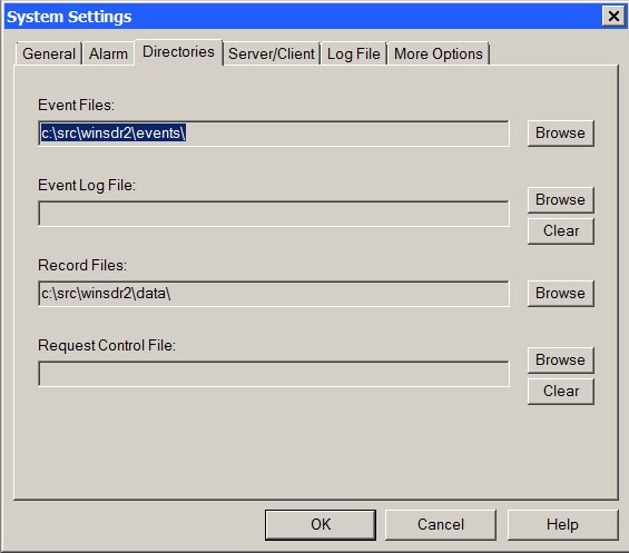
This tab of the System Settings dialog box is used to set various directories locations.
Event Files:
Sets the root directory where the PSN formatted event files will be places. The event file, either created automatically or with the Real-time or Replay windows, will be placed in a sub directory based on the year and month (drive:\Root_Directory\YYMM\). Use the Browse button to change or create the new directory. The directory can be located on another computer system by using a LAN and remote drive sharing. PSN formatted event files can be viewed and analyzed with WinQuake.
Event Log File:
If a directory is placed in this field, WinSDR will create a file called EVENT.LOG in the directory whenever WinSDR saves event files. In the EVENT.LOG file, WinSDR will place the UTC time that the files were saved, the number of files saved, the directory where the files were saved, and then the event file name(s). Fields are delimited by a coma. The application using the event log file may delete the file after using it. If the file is already in the directory, WinSDR will append the new event information to the end of the file. A typical line in the EVENT.LOG file will look like this:
03/17/02 00:38:06,2,c:\tmp\0203\,lcv.psn,lc8.psn
Record Files:
Sets the directory location for the daily record file. The daily record file holds the raw data from the A/D board. A new record file is created each day at 00:00 UTC. The directory holding the record files should be a drive on the same system that is running WinSDR. Using a LAN network and disk sharing, it is possible to place the record files on another system. The problem with this arrangement is your LAN and remote computer must be working all of the time. If the WinSDR system can not save data to the remote drive, do to the LAN not working or the remote system being down, data will be lost. It will also take longer for the Replay and Real-time windows to read the data from the remote disk. Use the Browse button to change or create the new directory.
Request Control File:
Sets the directory that WinSDR will use to monitor for a request file. See Request Event File documentation for more information on this option. Use the Browse button to change or create the new directory or the Clear button to clear this field.
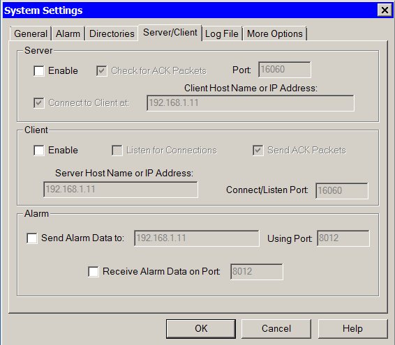
This tab of the System Settings dialog box is used to control the Server/Client TCP/IP settings. See this page for more information.
Server Group:
Enable Check Box:
This check box enables the TCP/IP Server feature.
Check for ACK Packets Check Box:
If enabled, WinSDR will check for acknowledge packets from the client. If no acknowledge packet is received for 2 minutes the connection will be closed.
Listen/Connect Port Edit Box:
The TCP/IP listen/connect port is the port that WinSDR will listen on for client connections. It will also be the port used to connect to a remote system is the Connect to Client at feature is enabled. This number can be in the range of 1 to 65535.
Connect to Client at Check Box and Edit Field:
If enabled, WinSDR will attempt to connect to the client specified in the edit field and after the connection is established send the ADC data to the client. If this feature is disable WinSDR will listen for client connections.
Client Group:
Enable Check Box:
This check box enables the TCP/IP Client feature.
Listen for Connections Check Box:
If enabled WinSDR will listen for server connections rather then initiate the connection.
Send ACK Packets Check Box:
If enabled, WinSDR will send acknowledge packets to the server to let it know that the remote system is receiving data packets.
Server Host Name or IP Address Edit Box:
This edit box is used to enter the host name (Example: data.mydomain.com) or the IP address (Example: 10.0.0.3) of the WinSDR server system.
Connection or Listen Port Edit Box:
The connection or listen port is the TCP/IP port that will be used to connect to the WinSDR server system. If the Listen for Connections feature is enabled WinSDR will listen for connection of the port number. The port number must match the Listen/Connect Port number in the Server settings group. This number can be in the range of 1 to 65535.
Alarm Group:
Send Alarm Data To Check Box:
This enables/disables the sending of alarm trigger information to a remote WinSDR system.
Send Alarm Data Edit Edit Box:
The host name (Example: data.seismicnet.com) or IP Address (Example: 192.168.1.2) of the remote system that will receive the trigger information.
Using Port Edit Box:
This is the TCP/IP port number to use when connecting to the remote system to transfer the trigger information.
Receive Alarm Data on Port Check Box:
If check, WinSDR will listen for remote alarm trigger information.
Receive Alarm Data on Port Edit Box:
This is the TCP/IP port number to use when listening for remote trigger information.
More information on the Remote Alarm Trigger feature can be found here.
[Top]
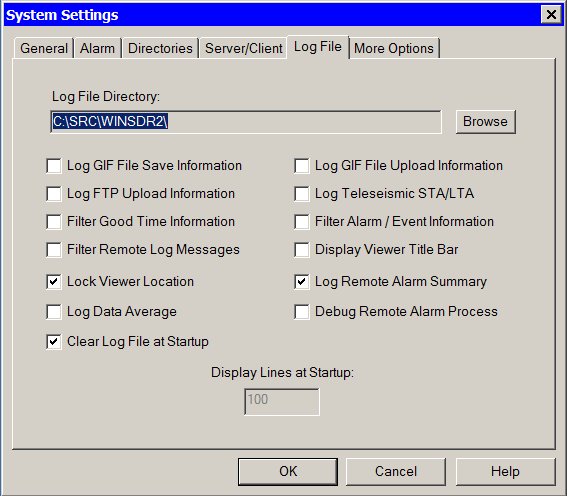
This tab of the System Settings dialog box is used to control the location of the winsdr.log file and what information will be saved in the log file and viewed in the Log File Viewer window.
Log File Directory:
Sets the directory where the debug log file (winsdr.log) will be located. This directory can be located on a local or remote drive. Use the Browse button to change or create the new directory.
Log GIF File Save Information Check Box:
If checked, WinSDR will save more GIF file generation messages in the log file.
Log GIF File Upload Information Check Box:
If checked, WinSDR will save more GIF file upload information messages in the log file.
Log FTP Upload Information Check Box:
If checked, WinSDR will save FTP upload information messages in the log file for both GIF file and event file uploads.
Log Teleseismic STA/LTA Check Box:
Displays and saves teleseismic trigger information in the log file.
Filter Good Time Information Check Box:
If checked, WinSDR will filter out normal time reference information messages generated by the A/D board. Time error messages will not be filter out..
Filter Alarm / Event Information Check Box:
If checked, WinSDR will filter out messages from the alarm / event detection process.
Filter Remote Log Messages:
Used when WinSDR is running in the TCP/IP Client mode. If checked, log messages generated at the WinSDR server system will be filtered from the local client's log file and display window.
Display Viewer Title Bar Check Box:
Toggles the Log File Viewer title bar on or off. By turning the title bar off, the viewer occupies less room on the desktop. When the title bar is turned off, the viewer can be moved by placing the mouse on the frame window and pressing and holding the left button. The title bar can also be toggled by double clicking on the window frame.
Lock Viewer Location Check Box:
If checked, the Log File Viewer will move with the main WinSDR window. If not checked, the viewer is stay in the same location on the desktop when the main WinSDR window is moved.
Log Remote Alarm Summary:
If checked, WinSDR will log summary remote alarm triggering information.
Debug Remote Alarm Process:
If checked, WinSDR will log debug remote alarm triggering information.
Log Data Average:
If checked, WinSDR will calculate the average ADC or CDC (VolksMeter) counts over a one minute period for each channel and save this information to a file named DataAverage.log. This information is also displayed in the Log File Viewer. The average is the raw data from the ADC or VolksMeter Interface board before any digital filtering. The DataAverage.log file is located in the WinSDR directory.
A typical entry in the log file looks like this:
12/27/06,04:52:42,LCTST,-1123784
The line contains the Date, Time, Sensor ID and data average in ADC or CDC counts.
Clear File at Startup Check Box:
If checked, WinSDR will delete the current log file at program startup.
Display Lines at Startup Edit Box:
This edit box controls how many lines of the log file that will be displayed in the Log File Viewer at program startup. This edit box will only be enabled if the Clear File at Startup check box is disabled.
[Top]
More Options Settings:
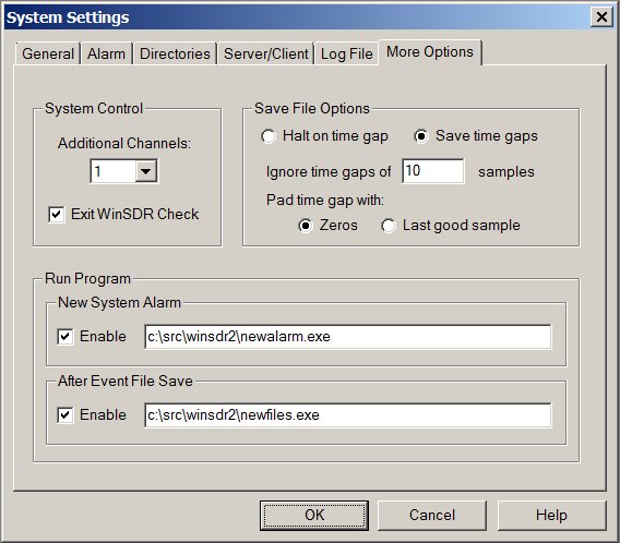
This tab of the System Settings dialog box is used to control more WinSDR options and features.
System Control Group:
Additional Channels Select Box:
This feature is used to derive additional channels from the real data channels recorded by the ADC board. Just like a real ADC channel a derived channel can be filtered before the data is saved to the daily record file. With this feature the user can create a channel that is filtered and also save the raw data from the sensor.
Save File Options:
Halt on time gap / Save time gaps Radio Buttons:
This radio buttons control how WinSDR saves event files from the daily record files when a gap in the data is detected. If Halt on time gap is selected WinSDR will stop saving the event file when a data gap is detected. If Save time gaps is selected WinSDR will continue to save data into the event file from the daily record file if a gap is detected.
Ignore time gaps of Edit Box:
The number of samples to ignore when a time gap is detected.
Pad time gap with Zeros or Last good sample Radio Buttons:
Controls how WinSDR fills in the gap when a hole in the data is detected. If Save time gaps is selected WinSDR can fill in the gap with zeros or the last good sample value.
Run Program Group:
This is a new feature in version 4.7.4. It allows the user to run a user supplied program or batch file when WinSDR goes into an alarm state or after the program saves event files. See Running a Program for more information. The Enable check box before each Edit Box is used to turn on or off the running of the program.
New System Alarm Edit Box:
Specifies what program to run when WinSDR goes into an alarm state. The input parameters to the program is the alarm type, either Normal or Teleseismic, and the channel names that triggered the alarm.
After Event File Save Edit Box:
Specifies what program to run after WinSDR saves one or more event files. The input parameters to the program are the event file names WinSDR saved to disk.
[Top]
Time Adjust Mode and Time Adjust Interval Information:
The Time Adjust Interval count is used to compensate for the timing
reference crystal oscillator on the Serial/USB Output A/D or VolksMeter Interface board not being exactly
8.000 MHz. The A/D board uses a 500 us interrupt generated by the reference oscillator. If the oscillator is a little fast or slow, the
time of day will slowly drift. By adding or dropping 1 millisecond at some
interval, it is possible to compensate for the oscillator being off frequency.
The Add/Drop number is the number of milliseconds to wait before a millisecond
time period is added to or dropped from the time accumulator. The time adjustment
information is stored in a file called time.dat. This file is located
in the root directory of WinSDR. If you use one of the time reference options (GPS, WWV, WWVB, or Comm
Port), WinSDR will calculate the Add/Drop interval number and direction (add
or drop) for you. If you can dedicate an inexpensive short-wave receiver
turned to one of the WWV stations you will be able to keep your time within
+-15ms or less. You will probably need to run a long wire antenna so you can
receive the station clearly enough for WinSDR to lock on the 800 ms tone sent
at the top of the minute. See the WWV Time Correction
Option for more information.
PSN-ACCEL and PSN-ADC24 Time Keeping:
The PSN-ACCEL and PSN-ADC24 boards use a different method to keep the time accumulator on the ADC board locked to GPS time. These boards use a Voltage Controlled Oscillator (VCO) for time keeping rather then use the Add/Drop time method documented above. The VCO drives both the CPU's clock and the clock needed by the 24-Bit sigma-delta ADC chips. This feature is only used if the ADC board is connected up to a GPS receiver. As WinSDR detects the time on the ADC board drifting from GPS time the VCO frequency is changed to compensate for the change in frequency of the crystal oscillator. In the WinSDR.log file you will see reference to the VCO percentage. This is the percentage of the voltage driving the VCO and is in the range of 0 to +5 volts with 50% being around 2.5 volts.