Contents:
- Usage
- Trace Display
- Event Detection
- Integrate / Filter Control
- Channel Control
- Save File
- Sensor Information
Channel Spin Control:
Changes the current channel number.
Save As Button:
Used to save the current channel settings to a file. The channel settings file should end in .ini.
OK Button:
Closes the dialog box. New information entered will be used by WinSDR.
Cancel Button:
Closes the dialog box without making any changes to the channel settings.
Help Button:
Opens this documentation.
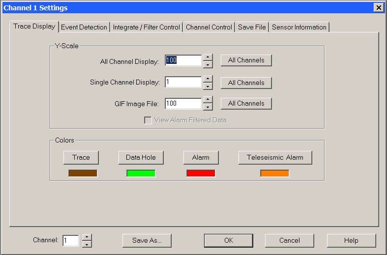
This tab of the Channel Settings dialog box is used to control the trace Y-Scale and colors.
Y-Scale Group Box:
All Channel Edit Box:
Sets the vertical (amplitude) compression / expansion of the trace when the display window is displaying all channels. 1 = no compression or expansion. A positive number will compress and a negative number will expand the data.
Single Channel Edit Box:
Sets the vertical (amplitude) compression / expansion of the trace when the display window is displaying this channel. 1 = no compression or expansion. A positive number will compress and a negative number will expand the data.
GIF Image File Edit Box:
Sets the vertical (amplitude) compression / expansion of the trace when WinSDR creates GIF file images of the data. 1 = no compression or expansion. A positive number will compress and a negative number will expand the data.
All Channels Button:
This button can be used to set the All Channels, Single Channel and GIF Image File Y-Scale to the same value for all of the channels you are recording.
View Filtered Data Check Box:
If checked, WinSDR will display the filter data instead of the raw data from the ADC board. This check box will be disabled if the high-pass and low-pass filters are not enabled.
Colors Group:
Trace Button:
Sets the normal trace color for this channel.
Data Hole Button:
Used by the Replay window to indicate a hole in the data. The first minute of data after a time hole in the record file will be this color.
Alarm Button:
Sets the trace color when the channel is in an alarm or triggered state.
Teleseismic Alarm Button:
Sets the trace color when the channel is in a teleseismic event alarm or triggered state.
[Top]
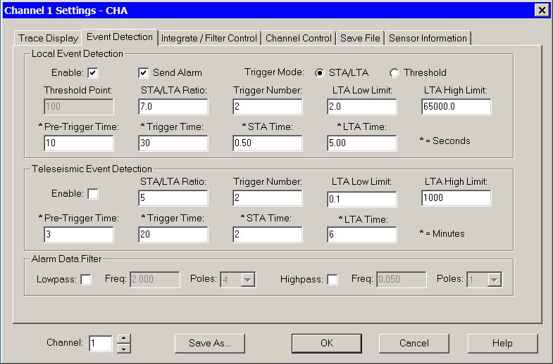
This tab of the Channel Settings dialog box is used to control event detection and digital filter parameters.
Local Event Detection Group Box:
Enable Check Box:
If checked, WinSDR will enable triggering and alarm functions for the channel based on the Triggering Mode.
Send Alarm Check Box:
This is part of the Remote Alarm feature. If check, WinSDR will send alarm trigger information to a remote WinSDR system.
Triggering Mode:
If STA/LTA (Short/Long Term Averaging) triggering will be enable is this check box is selected and Threshold triggering will be enable if this check box is selected.
Threshold Point Edit Box:
Used for simple amplitude alarm triggering. Sets the threshold for the selected channel, if the alarm feature is enabled. Enter a positive number above your normal background noise level.
STA/LTA Ratio Edit Box:
Sets the STA/LTA threshold point. See WinSDR STA/LTA Triggering for more information.
Trigger Number Edit Box:
This field is used for both simple threshold (amplitude) and STA/LTA triggering modes. Sets the number of data points that must be exceeded above the Threshold Point or STA/LTA Threshold to trigger an alarm and auto save the event file(s). A number between 20 and 50 should be fine for amplitude triggering and 2 to 4 for STA/LTA triggering. See WinSDR STA/LTA Triggering for more information.
LTA Low Limit Edit Box:
Sets LTA minimum value. See WinSDR STA/LTA Triggering for more information.
LTA High Limit Edit Box:
Sets LTA maximum value. See WinSDR STA/LTA Triggering for more information.
Pre-Trigger Time Edit Box:
Sets the time in seconds the channel stays in the pre-trigger state. See WinSDR STA/LTA Triggering for more information.
Trigger Time Edit Box:
Sets the time in seconds the channel stays in an alarm or triggered state. See WinSDR STA/LTA Triggering for more information. This field is used for both simple threshold (amplitude) and STA/LTA triggering modes.
STA Time Edit Box:
Sets the STA average time, in seconds. Fractions of a second can be entered. See WinSDR STA/LTA Triggering for more information.
LTA Time Edit Box:
Sets the LTA average time, in seconds. Fractions of a second can be entered. See WinSDR STA/LTA Triggering for more information.
Teleseismic Event Detection Group Box:
Enable Check Box:
If checked, WinSDR will attempt to detect teleseismic events.
STA/LTA Ratio Edit Box:
Sets the STA/LTA threshold point. See WinSDR STA/LTA Triggering for more information.
Trigger Number Edit Box:
This field is used for both simple threshold (amplitude) and STA/LTA triggering modes. Sets the number of data points that must be exceeded above the Threshold Point or STA/LTA Threshold to trigger an alarm and auto save the event file(s). A number between 20 and 50 should be fine for amplitude triggering and 2 to 4 for STA/LTA triggering.
LTA Low Limit Edit Box:
Sets LTA minimum value.
LTA High Limit Edit Box:
Sets LTA maximum value.
Pre-Trigger Time Edit Box:
Sets the time in minutes the channel stays in the pre-trigger state.
Trigger Time Edit Box:
Sets the time in minutes the channel stays in an alarm or triggered state.
STA Time Edit Box:
Sets the STA average time, in minutes.
LTA Time Edit Box:
Sets the LTA average time, in minutes.
Digital Filter Group Box:
Lowpass Check Box:
Enables lowpass filtering of the data going to the alarm / event detection process.
Lowpass Frequency Edit Box:
Sets the lowpass filter cutoff frequency.
Lowpass Poles:
Sets the number of poles, or the steepness of the filter, used to attenuate the incoming data.
Highpass Check Box:
Enables highpass filtering of the data going to the alarm / event detection process.
Highpass Frequency Edit Box:
Sets the highpass filter cutoff frequency.
Highpass Poles:
Sets the number of poles, or the steepness of the filter, used to attenuate the incoming data.
[Top]

This tab of the Channel Settings dialog box controls various filters that can be applied to the incoming data. Any filters that are enable on this dialog box tab directly effect the incoming data. The daily record files as well as event files produced by WinSDR will have the filtered data in it. By deriving more data channels both the raw and filtered data can be saved to disk in the daily record files. See the System Settings dialog box for more information on deriving additional data channels.
Period Extender Filter Group:
Enable Check Box:
Used to enable the filter. Integration must be disabled.
Pendulum Frequency:
The frequency or period of the sensor. The number entered is in Hertz not seconds. Example: A sensor with a period of 2 seconds would have a value of 0.5 in this field.
Pendulum Q:
The Pendulum Q Factor. If the sensor is properly damped this value should be 0.7
High-Pass Filter Frequency:
This controls the frequency of the high-pass filter that is used to set the low frequency end of the filter. It should be set to a frequency below the Pendulum Frequency above. A good starting point would be two octaves below the natural period of the sensor.
Filter Q:
The Q of the High-Pass filter. Normally set to 0.707.
Integrate Data Group:
Enable Check Box:
Used to enable data integration. Period Extender Filter must be disabled.
Enable High-Pass Filter:
Enables a pre integration High-Pass filter
High-Pass Frequency:
Frequency of the High-Pass filter.
High-Pass Poles:
Number of poles for the High-Pass filter
Post Digital Filter Group:
This set of filters can be used to "clean up" the data after the Period Extender Filter or Data Integration. These filter can be enabled even if the Period Extending and Integration are disabled. Since these filters are performed on the incoming data that will be saved in the daily record files, high and/or low frequency information will be lost do to the filtering process and can not be recovered. By setting up WinSDR to have derived channels, both the raw data from the sensor as well as filtered data can be saved to disk. This way GIF file images and event files can be created from both the raw and filtered channels.
Enable Low-Pass Check Box:
Enables Low-Pass filtering of the incoming data.
Low-Pass Frequency Edit Box:
Sets the Low-Pass filter cutoff frequency.
Low-Pass Poles:
Sets the number of poles, or the steepness of the filter, used to attenuate the incoming data.
High-Pass Check Box:
Enables High-Pass filtering of the incoming data.
High-Pass Frequency Edit Box:
Sets the High-Pass filter cutoff frequency.
High-Pass Poles:
Sets the number of poles, or the steepness of the filter, used to attenuate the incoming data.
[Top]
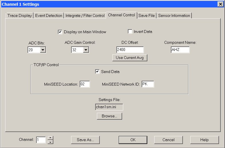
This tab of the Channel Settings dialog box is used to control various parameters of the selected channel.
Display on Main Window Check Box:
Enables or disables the displaying of the selected channel on the real-time window when all channels are being displayed. Note: Data is still recorded if the channel is not displayed and event files will be produced when the system detects an event. The Replay mode can also be used to extract event files.
Invert Data Check Box:
Inverts the data for this channel.
ADC Bits Select Box:
Selects how many ADC (or CDC Bits for the VolksMeter Sensor) to use from the ADC board. The options for the PSN-ADC-SERIAL/PSN-ADC-USB 16 Bit board are 12 and 16 bits. For the VolksMeter, PSN-ACCEL and PSN-ADC24 boards the options are 16 to 24 bits.
ADC Gain Control Select Box:
Controls the Programmable Gain Amplifier's gain on the PSN-ACCEL and PSN-ADC24 boards. The options are: 1, 2, 4, 8, 16, 32 or 64. This field will be disabled and set to a gain of 1 for PSN-ADC-SERIAL/PSN-ADC-USB 16 Bit boards and the VolksMeter interface board.
DC Offset Edit Box:
Used to correct for any DC offset on this channel.
Use Current Average:
Used to set the DC Offset edit box above with the current inverted data average. The average of each channels is started when the Channel Settings dialog box is opened. The user should wait awhile before using this feature to let WinSDR build up an average for the channel.
Component Name Edit Box:
Sensor Component Name. Used to describe the sensor. Example: BHZ or SHN
TCP/IP Control Group:
Send Data Check Box:
If checked, WinSDR will send data to a TCP/IP client when the client requests ADC data packets.
MiniSEED Location:
Used to fill in the two character Location field in the MiniSEED header.
MiniSEED Network ID:
Used to fill in the two character Network field in the MiniSEED header.
Settings File:
Used to select the settings file for this channel. Use the Browse button to select a new *.ini file.
[Top]
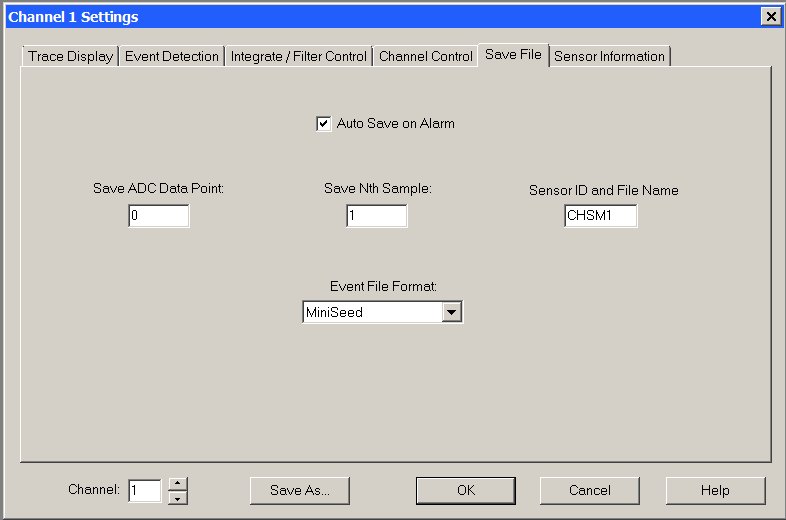
This tab of the Channel Settings dialog box is used to control various parameters when WinSDR saves event files.
Auto Save on Alarm Check Box:
If checked, WinSDR will save an event file for this channel when an event is detected.
Save ADC Point Edit Box:
Used to filter automatically saved event files. If a value other than 0 is entered, the peek data count during an alarm for this channel must be higher then the number entered in this field before an event file will be saved. A value of 0 disables event file filtering. This setting should only be used if more than one channel is being recorded.
Save Nth Sample Edit Box:
When WinSDR automatically saves an event file it will use this number for the Save Nth value. Save Nth controls the sample rate of the event file.
Sensor ID and File Name Edit Box:
Sets the sensor ID string and event file extension from this channel. The sensor ID string should be 3 to 6 characters long.
Event File Format List Box:
Sets the event file output format. Currently WinSDR can save event files in the following formats: PSN, SAC Binary and MiniSeed with Steim 2 encoding.
[Top]
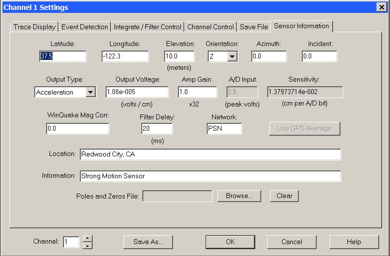
Latitude Edit Box:
Enter the Latitude of the sensor in degrees and decimal point not in degrees, minutes, seconds. Use a negative number for the Southern Hemisphere.
Longitude Edit Box:
Enter the Longitude of the sensor in degrees and decimal point not in degrees, minutes, seconds. Use a negative number for the Western Hemisphere.
Elevation Edit Box:
Elevation of the sensor in meters above or below (negative number) sea level. Use -12345.0 if unknown.
Orientation Select Box:
Set to Z for a vertical sensor, N for a North-South oriented sensor, E for a East-West sensor or ? if unknown.
Azimuth Edit Box:
Sensor azimuth angle in degrees with respect to the north through east. For a N-S or vertical sensor use 0. For a E-W sensor use 90. Set to -12345.0 if unknown.
Incident Edit Box:
Sensor incident angle in degrees with respect to vertical. For a N-S or E-W sensor use 90. For a vertical sensor use 0. Set to -12345.0 if unknown.
Output Type Select Box:
Select the sensor output type to either Acceleration, Velocity, Displacement or Unknown. See below for more information.
Output Voltage Edit Box:
Output voltage of the sensor in volts per centimeter of movement.
Amp Gain Edit Box:
Gain of the amplifier/filter channel that is between the sensor and the ADC input. For PSN-ACCEL and PSN-ADC24 boards, the current ADC Gain Controlled value in the Channel Control tab will be displayed below this edit box.
A/D Input Edit Box:
Specifies the maximum peak input voltage of the ADC channel. For the PSN-ADC-SERIAL this is usually set to 10 volts. For PSN-ACCEL and PSN-ADC24 boards this value will be fixed at 2.5 volts.
Sensitivity Edit Box:
The sensitivity of the sensor if known. See below for more information.
WinQuake Mag Corr Edit Box:
A floating point number used by WinQuake to calculate magnitude. See the WinQuake documentation for more information.
Filter Delay Edit Box:
Used to compensate for any propagation delay through the low-pass filter for this channel. The number entered is in milliseconds. See this below for more information.
Network Edit Box:
Network affiliation. Example: PSN
Use GPS Average Button:
This button will set the sensor's latitude, longitude and elevation fields to the average GPS position data. The button will only be enabled if WinSDR is displaying the GPS Location dialog box.
Location Edit Box:
Sensor location string. Please keep as short as possible. Example: Redwood City, CA USA
Information Edit Box:
Sensor information string. Example: 12 Second Lehman or Geospace HS10 1Hz Geophone
Poles and Zeros File:
If specified, WinSDR will save the Poles and Zeros (frequency response information) contained in the file into the PSN Event file. Example of a Poles and Zeros file. Use the Browse button to locate the file and the Clear button to remove the file.
[Top]
Sensor Sensitivity Field:
The Sensor Sensitivity field number depends on the Sensor Output Type field. If the sensor output is acceleration, sensitivity is in cm/sec/sec per A/D bit, if the output is velocity cm/sec per bit and if the output is displacement in cm per bit. This web page can be used to calculate the sensitivity number if you know the output voltage level of your sensor.
Sensor Filter Delay Field:
The Filter Delay setting is used to compensate for the propagation delay of the signal through the low-pass filter connected between the sensor and the A/D card. This is done by subtracting from the start time of the event file the number of milliseconds entered in this field. To measure the delay of your filter you will need a signal generator with a square wave output and a oscilloscope with two channels (or you could use two WinSDR channels). Feed the square wave into the amp / filter card. With the O-Scope or WinSDR look at the input signal with one channel and the output of the filter with the other. Measure the difference between the input and output signal in milliseconds and enter that number in the Filter Delay field for the channel. If you are using my Amp / Filter board with a 10 Hz low-pass filter you should use a value of around 50 milliseconds. For PSN-ACCEL and PSN-ADC24 boards running at 100 SPS or higher a value of 20 milliseconds can be used.