Software: WinSDR Version 4.7.x Linux Driver Library and Windows DLL
Enclosures for the PSN-ADC-SERIAL / PSN-ADC-USB Board
Firmware Upgrade Information for the Garmin GPSx 18 LVC Receiver
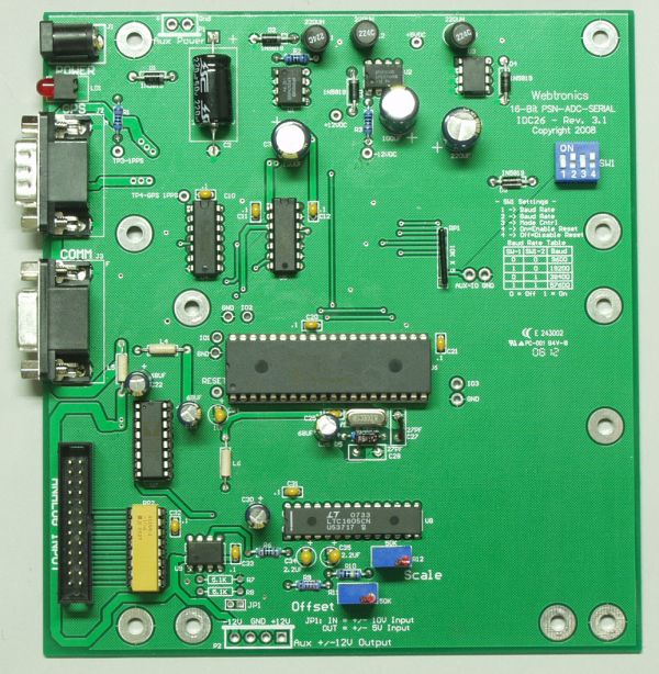
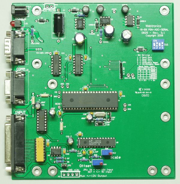
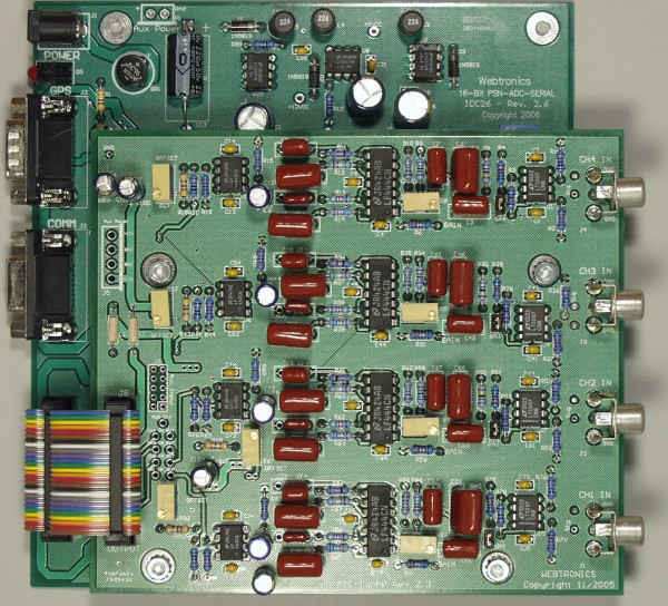
PSN-ADC-SERIAL Version III Board with 26 Pin Ribbon Connector Header and DB25 Pin Connector
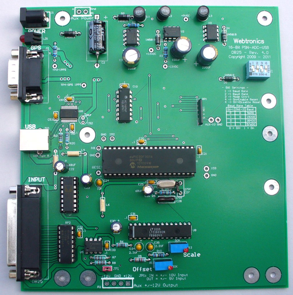
PSN-ADC-USB Version III Board with DB25 or 26 Pin Header
Click on image for larger view
Notes:
- At 500 SPS the board can record up to 4 channels
- Other input impedance possible by changing one resistor pack
The PSN-ADC-SERIAL or PSN-ADC-USB boards with DB25 Connector come with one DB-25 male connector and connector hood.
To order a board please contact us at the email address below.
The Analog to Digital converter chip on the PSN-ADC-SERIAL / PSN-ADC-USB board has an internal noise level of +- 3 counts. With the use of oversampling, the internal noise level of the chip can be averaged out to produce a true 16-Bit (96db) dynamic range. The amount of oversampling depends on the sample rate. See table below:
SPS
Average #
SPS
Average #
10
800
200
40
20
400
250
16
50
200
500
16
100
80
There are two versions of the PSN-ADC-SERIAL and PSN-ADC-USB boards. The boards are identical except for the Analog Input connector and location on the board. The board with the DB25 right angle connector is for customers who only need the ADC board. This version allows access to all of the connectors at the edge of the board. The board with the 26 pin ribbon connector header can be used with the PSN-ADC-EQAMP Amplifier / Filter board with mating 26 pin header connector. This arrangement produces a module that can be mounted in a off-the-self box or this custom made metal enclosure.
The difference between the PSN-ADC-SERIAL and PSN-ADC-USB boards is the interface between host computer and the ADC board. The PSN-ADC-SERIAL board uses a RS-232 interface and the PSN-ADC-USB use a USB interface to the host computer. With the Virtual COM Port driver from FDTI the PSN-ADC-USB board emulates a standard RS-232 COM Port so datalogger programs like WinSDR see a common interface.
WinSDR (Download) can be used to record data using the PSN-ADC-SERIAL / PSN-ADC-USB Version III ADC board. This program is included with the purchase of the board.
This Windows DLL Driver and Linux Library ( pdf version ) can be used by programmers who would like to write their own datalogger program or add the A/D board to an existing program. The DLL Driver zip file or Linux Library includes an example, written in VC++ 8.0, showing how to use the PSNADBoard.DLL file.
Earthworm, a powerful seismic software package that can run under various operating systems, can now receive data using the PSN-ADC-SERIAL / PSN-ADC-USB board or WinSDR. See this link for more information.
Garmin is now shipping a new version of their OEM GPS 18 LVC receiver. The new receiver, the GPSx 18 LVC, has better sensitivity then the older model. The new receiver required a minor change to the PSN-ADC-SERIAL firmware to operate properly. Version III ADC board users should use firmware version 1.2. Version II ADC board users should use firmware version 2.8. To upgrade the firmware, download the appropriate zip file, unzip, copy the .hex file to your WinSDR install directory and then follow these directions. Version III ADC boards started shipping with firmware version 1.2 December 8 2008.
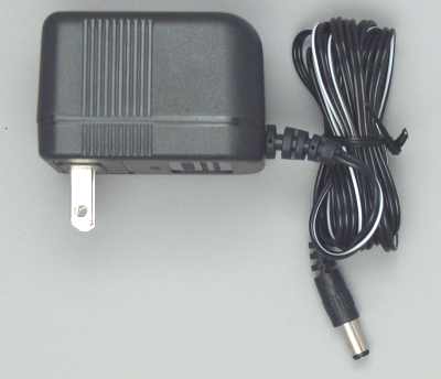
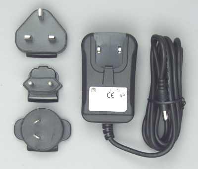
Power Supply Connector J1 and Power Requirements:
The power connector on the board is a standard 2.1mm X 5.5mm male jack. Positive voltage must be applied to the center pin. A diode on the board will prevent damage if the power is reversed.
The DC input range is 15 volts to 28 volts. At 15 VDC the board draws ~70 ma, at 24VDC ~48 ma. With a Garmin GPS 18 Sensor connected to the board, the current draw is 100 ma at 15 VDC and 65 ma at 24 VDC.
Note: If the user supplies their own power supply the voltage across the large capacitor C2 should be checked to verify there is enough voltage for proper operation. The voltage should be between 14.6 and 28 VDC, with ~18 VDC being optimum. If the voltage is too low, the onboard DC regulators will not operate properly. If the voltage is too high, you will exceed the maximum voltage level of the parts on the A/D board.
GPS Comm Connector J2:
This connector is a 9 pin, DB-9 male connector used to communicate to a GPS receiver. A straight through serial cable should be used between the A/D board and the GPS's receiver interface board. See /gps/index.html for a GPS timing system compatible with the PSN-ADC-SERIAL / PSN-ADC-USB board. The connector has the following pinout:
- Pin 1 - CD (Carrier Detect) Input, Used for the 1 PPS signal from the GPS receiver
- Pin 2 - Receiver Data Input from the GPS Receiver
- Pin 3 - Transmit Data Output to the GPS Receiver
- Pin 4 - +5 VDC for Garmin GPS 16/18 Power
- Pin 5 - Ground
- Pin 7 - Ground for Garmin GPS 16
- Pins 6, 8 and 9 - Not Connected
PSN-ADC-SERIAL Comm Connector J3:
This connector is a 9 pin DB-9 female connector used to communicate to the PC running WinSDR. A straight through serial cable should be used between the A/D board and the your computer. The connector has the following pinout:
- Pin 1 - Not Connected
- Pin 2 - Transmit Data Output
- Pin 3 - Receive Data Input
- Pin 4 - DTR (Data Terminal Ready) Input - CPU Reset Line
- Pin 5 - Ground
- Pin 6 - Not Connected
- Pin 7 - Not Connected
- Pin 8 - Not Connected
- Pin 9 - Not Connected
The DTR line ( Pin 4 ) is used to reset the CPU on the A/D board. This line should be below 2 VDC for normal operation. If the LED on the board does not come on, it may be do to this line holding the CPU in the reset state. Position 1 of Switch SW1 can be used to disable this feature. If disabled, off position, the host computer can not reset the CPU on the A/D board.
PSN-ADC-USB Interface J3:
This USB Type B connector is used to communicate with the PC. The USB interface chip used on the A/D board is a FTDI FT232RL. Windows or Linux drivers (32-Bit or 64-Bit) can be downloaded from here.
Analog Input / Power Output Connector J4:
The 25 pin DB-25 female connector has the following pinout:
- Pin 1 - Analog Input Channel 1
- Pin 2 - Analog Input Channel 2
- Pin 3 - Analog Input Channel 3
- Pin 4 - Analog Input Channel 4
- Pin 5 - Analog Input Channel 5
- Pin 6 - Analog Input Channel 6
- Pin 7 - Analog Input Channel 7
- Pin 8 - Analog Input Channel 8
- Pin 9 - Analog Ground
- Pins 10 and 11 - +12 VDC Output Power. 75 MA Max.
- Pin 12 - Not Connected
- Pin 13 - Power Ground
- Pins 14, 15, 16, 17, 18, 19, 20 and 21 Analog Grounds for Channels 1 to 8
- Pin 22 - Not Connected
- Pins 23 and 24 - -12 VDC Output Power. 75 MA Max.
- Pin 25 - Power Ground
The 26 pin .1 inch dual row header has the following pinout:
- Pin 1 - Analog Input Channel 1
- Pin 3 - Analog Input Channel 2
- Pin 5 - Analog Input Channel 3
- Pin 7 - Analog Input Channel 4
- Pin 9 - Analog Input Channel 5
- Pin 11 - Analog Input Channel 6
- Pin 13 - Analog Input Channel 7
- Pin 15 - Analog Input Channel 8
- Pins 2, 4, 6, 8, 10, 12, 14 and 16 Analog Ground for Channels 1 to 8
- Pins 19 and 21 - +12 VDC Output Power. 100 MA Max.
- Pins 20 and 22 - -12 VDC Output Power. 100 MA Max.
- Pins 17, 18, 23, 24, 25, 26 Power Ground
Jumper JP1:
This jumper controls the input voltage range of the A/D converter. When the jumper is in, the input voltage range is +- 10 volts. With the jumper removed, the input range is +- 5 volts. The jumper controls all 8 analog input channels.
Switch SW1:
Switches 1 and 2 Control the Baud Rate. See Table Below. (Default = 38.4K)
Switch 3 On - Version II Emulation Mode - See Note Below
Switch 3 Off - Normal ModeSwitch 4 On - Allows the CPU on the ADC board to be reset by the host computer using J3 DTR pin 4 (Default)
Switch 4 Off - Host computer can not reset ADC CPU.
Baud Rate Table
SW1
SW2 Rate
Off
Off 9600 On
Off 19200 Off
On 38400 On
On 57600 Emulation Mode:
SW1 Switch 3 controls the output format of the ADC board. When enabled, Switch 3 On, the output format will resemble the Version II ADC board. This mode will allow software written for the older board to operate without modification. Users should use WinSDR version 4.1.5 or above with Switch 3 Off so WinSDR will know that you are using the new Version III board.
This page viewed times since
June 25, 2008